Analogue Systems
Polyphonic harmonic generator. 6 voice, 4 oscillator per note wavetable and additive synthesis engine. Additional features include fully functional polyphonic MIDI/CV converter with 4 programmable controller outputs and assignable gate function for programming S-trigger standard triggers and midi clock.

Just as the precise positions and shapes of the formants in a human voice allow you to identify the identity of the speaker as well as the vowel sound spoken, formants make the timbres of acoustic instruments consistent and recognisable from one instrument to the next. It therefore follows that recreating formants is a big step forward for synthesising many types of sounds.
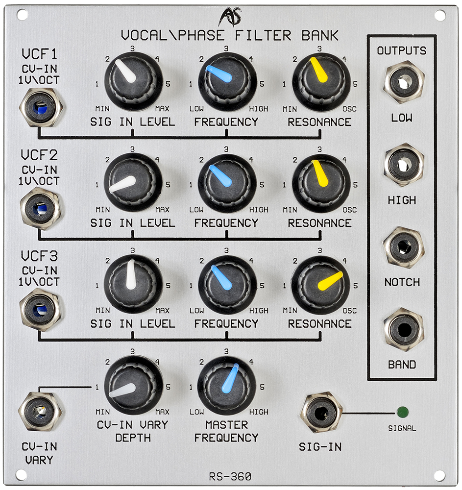
Normally, formant synthesis requires at least three formant filters per sound (see appendix 6) with appropriate CVs for each. The RS-360 provides all of this in a single module 24HP module. However, the RS-360 is more than just a formant filter. All three filters produce the four common filter characteristics: low-pass, high-pass, notch and band-pass, with summed outputs that offer the low-pass outputs of all three filters, the high-pass outputs of all three, and so on. You can also use the RS-360 as an effects unit. If you route different outputs (say, band-pass and notch) to two panned channels, you can produces stereo effects reminiscent of the flangers and phasers used in early multi-keyboards. Furthermore, you can use the three self-oscillating filters as multiple audio signal sources, or create unusual waveforms from the three ‘partials’.
The RS-360 provides three, parallel, resonant multi-mode filters with voltage control of each.
Filter Modes
It offers four filter modes. These are 24dB/Oct low-pass, 24dB/Oct high-pass, 12dB/Oct band-pass and 12dB/Oct notch filtering, with the cutoff frequencies (Fc) of the high-pass and low-pass outputs being the centre frequencies of the band-pass and notch outputs. Each of these filter characteristics is described in appendix 2. All four modes are available simultaneously from the appropriate output sockets.
Cutoff Frequency - Controlling the Filters Individually
You may control the cut-off frequencies of each of the filters individually using the FREQUENCY controls provided. When a given Frequency knob is in its fully anticlockwise position, the Fc it controls is approximately 30Hz. As you rotate that knob clockwise, Fc increases until, it its fully clockwise position,it exceeds 15kHz.You may also control a given Fc using the associated CV-IN 1V/OCT input. If you apply a CV conforming to the 1V/Oct standard, Fc will track the CV in exactly the same way as a standard VCO. If the CV is supplied from a keyboard then, in common parlance, the filter tracks the keyboard at 100% and, with the resonance at maximum, you can ‘play’ the filter as if it were a conventional oscillator.
Cutoff Frequency - Controlling the Filters Simultaneously
If you wish to modify the cut-off frequencies for all three filters simultaneously, you may do so using the MASTER FREQUENCY knob. You may also use the associated CV-IN VARY input. This socket and its associated DEPTH knob control all three filter Fcs simultaneously within the range ∞V/oct to approximately 0.4V/Oct. The former of these makes the input invariant to incoming CVs, while the latter makes it oversensitive compared to the CV-IN 1V/OCT input.
Resonance
Each filter offers resonance, or ‘Q’, that you control using its RESONANCE knob. In the fully anticlockwise position, Q is approximately zero, and there is no emphasis of the signal at Fc. As you rotate the knob clockwise, Q increases, whereupon every mode of that filter will accentuate the harmonics that lie close to the cut-off frequency. Increasing Q further, the filters will exhibit ringing, and will severely colour the signals passed through them. If you continue to increase the resonance beyond a certain point, the filter will begin to oscillate, and each mode will produce a sine wave at the cutoff frequency determined by the various controls. This oscillation is produced by all four audio outputs. The exact nature of the wave varies from mode to mode, and you can use these differences to create tonal variations when using the RS-360 as an oscillator bank.
Audio Signal Inputs and Outputs
The RS-360 has one audio signal input, SIG-IN, which accepts signals in the range ±10V. Individual LEVEL controls determine how much of the input signal is fed to each of the filters. An LED indicates when a signal is presented to SIG-IN. There are four outputs, one for each mode, and these each carry a signal in the range ±10V.