RS100
Moog-Type Ladder Filter
Filters are the means by which we modify sounds to create new sounds. The most common way in which they do this is by removing parts of the audio spectrum - attenuating the low frequencies and/or the high frequencies, or maybe by creating 'holes' in the spectrum. Other types of filter may enhance parts of the spectrum, or they may act in the time domain, removing sections of the signal rather than modifying its frequency response.
The most common filter in analogue synthesis is called the low-pass filter and its name exactly describes its function: it passes the part of the spectrum below its cut-off frequency, but attenuates or even removes those frequencies that lie above the cut-off frequency.
The most highly revered low-pass filter in analogue synthesis was developed by Dr Robert Moog in the late 1960s. It first appeared in the modular Moog synthesisers of that decade, but its finest hour came in 1970 with the appearance of the Minimoog. Largely because of its filter, this rather limited instrument has remained the standard by which all others are measured, and has survived nearly 30 years with its reputation intact as the most desirable of all integrated monophonic synthesisers.
Moog's filter used a circuit called a ladder network. In itself, there is nothing special about this, and many other filter designs are capable of emulating its response. However, Moog's circuit was flawed because it exhibited a small amount of distortion. Many engineers would have sought to correct this but Moog did not, perhaps because he recognised that the sound was musically pleasing. Indeed, if a synthesiser sounds like a Minimoog, it is called "warm" or "creamy". If it does not it will often be referred to as "thin" or "uninspiring".
The RS100 24dB/oct low-pass filter imitates the Minimoog's filter and exhibits almost identical characteristics in both the frequency domain (i.e. what it does to audio signals) and the time domain (i.e. its response over time to CVs). Below the cut-off frequency the response is approximately flat down to DC. With the filter fully open, it will pass signals approaching 20kHz.
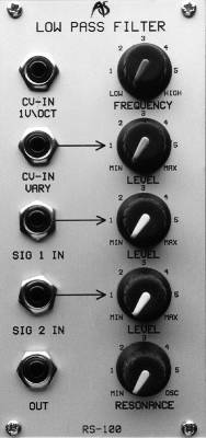
IN USE
Cutoff
Frequency
You can control the cut-off
frequency (Fc) using the FREQUENCY control. In its fully
anticlockwise position, Fc is approximately 30Hz. As you rotate the
knob clockwise Fc will increase until, it its fully clockwise position,
it exceeds 15kHz. These extreme positions are called 'closed' and 'open'
respectively. You may also control Fc using one or both of the CV
inputs:
CV-IN 1V/OCT
If you apply a CV conforming to the 1V/oct standard, Fc will track the CV in exactly the same way as an RS90 VCO would if you applied the same CV to its CV-IN 1V/OCT socket. If the CV is supplied from a keyboard then, in common parlance, the filter is tracking the keyboard 100% and, with the resonance at maximum, you can 'play' the filter as if it were a conventional oscillator.
CV-IN VARY
You may wish Fc to track incoming CVs at >100% or <100%, so the CV-IN VARY input is provided. This socket and its associated LEVEL control allow you to specify the filter's sensitivity to CVs within the range ×V/oct to approximately 0.4V/oct. The former of these makes the filter invariant to incoming CVs, while the latter makes it over-sensitive compared to the 1V/oct input.
Resonance
The RS100 has variable resonance, or 'Q'. As this is increased from its
minimum, the filter will accentuate Fc, and progressively attenuate
frequencies below Fc as well as those above it. As the resonance is
increased further, the RS100 will exhibit the aggressive 'ringing'
associated with Moog filters, and it will severely colour any signal
passed through it. At the highest Qs, the filter itself will begin to
oscillate, and even in the absence of any signal presented to its
inputs it will then act as a sine wave generator, the frequency
of which is Fc itself.
You can control 'Q' manually using the RESONANCE control. In its fully anticlockwise position, Q is approximately zero, and there is no emphasis of the signal at Fc. As you rotate the knob clockwise Q will increase until, it its fully clockwise position, the filter produces a sine wave of frequency Fc.
There is no voltage control of Q.
Inputs and
Outputs
The RS100 has two inputs: SIG 1 IN and SIG 2 IN, each with an associated
LEVEL control. The inputs accept signals in the range ±10v, and these
signals are mixed so that they can be filtered simultaneously.
The LEVEL controls offer unity gain in approximately the 2 o'clock position, marked '4' on the panel. At their fully anticlockwise position they attenuate the signal fully (MIN = -×dB gain) while at their fully clockwise position they offer a small gain. This (or, indeed, any high level signal) allows you to 'overdrive' the filter inputs for characteristic distortion.
There is a single output that carries a signal in the range ±10v.