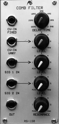
RS120
Comb Filter
INTRODUCTION
Many players and programmers believe that it is the filters that define an instrument’s sound, yet few look any further than the simple low-pass filter found on almost all analogue synthesisers. But endless tedious arguments about the relative merits of Moog's low-pass ladder filters or the various incarnations of ARP's 40xx equivalents obscure the fact that you create many of the most interesting sounds using some of the more obscure synthesiser filters.
After the low-pass filter, the most common synthesiser filter is the 'high-pass' filter, so called because it passes frequencies above the cut-off frequency, and attenuates those lying below it. Then there are the somewhat rarer and, by and large, more subtle band-pass and band-reject filters found only on more fully-featured instruments.
Band-pass filters - sometimes called 'formant filters' - allow you to select the part of the spectrum passed at their outputs. If you use two or more of these in parallel you can imitate the natural resonances of many instruments, and create remarkable imitations of human vowel sounds.
Band-reject filters - or 'notch filters' - create 'holes' in the spectrum and offer an altogether different range of sounds. A single notch is often not obvious to the ear, but if you start to sweep this up and down the spectrum you will hear the characteristic effect of accentuating and removing different frequencies at different times. This is the basis of most flanging effects, and if you modulate multiple notch filters you can imitate a wide range of flanging, phasing, and chorus effects.
Comb filters, which are a special case of multiple notch filters, are the rarest of all analogue synthesiser filters. Often found in cheap effect units, they are usually described as analogue delay lines and, as explained in Appendix 4, an ADL is simply a different name for the same device.
The RS120 is a comb filter based upon a BBD (bucket brigade device) analogue delay line. It has a frequency response of approximately 30Hz to 5kHz at its output, so it is not suitable for generating or processing sounds with a wide bandwidth, but it nevertheless enables you to coax unique sounds from the Integrator.
IN USE
Delay
Time
You adjust the fundamental frequency of the comb filter (Fc) using the DELAY
TIME control. In its fully anticlockwise position, the delay is
approximately 25mS, resulting is an Fc of approximately 40Hz. As you
rotate the knob clockwise the delay time will decrease until, it its fully
clockwise position, it reaches approximately 2.5mS and Fc is
approximately 4000Hz. You may also control the DELAY TIME
and, therefore, Fc using one or both of the CV inputs:
CV-IN
1V/OCT
If you apply a CV conforming to the 1V/oct standard, Fc will track the CV in
exactly the same way as an RS90 VCO would if you applied the same CV to
its CV-IN 1V/OCT socket. If the CV is supplied from a keyboard then, in
common parlance, the fundamental frequency is tracking the keyboard
100%.
CV-IN
VARY
You may wish Fc to track incoming CVs at >100% or <100%, so the CV-IN
VARY input is provided. This socket and its associated LEVEL control
allow you to specify the filter's sensitivity to CVs within the range
×V/oct to approximately 0.4V/oct. The former of these makes the filter
invariant to incoming CVs, while the latter makes it over-sensitive
compared to the 1V/oct input. The DELAY TIME is calibrated from 2.5mS
to 25mS. Depending upon the revision of RS120 in your Integrator, the
actual delay may have this range, or one of 5mS to 50mS. If the latter, this
will halve the fundamental frequency of the comb filtering effect, but
have no other affect on its operation.
Resonance
The RS120 has variable
feedback or "regeneration". This is equivalent to the resonance of
a more conventional filter. As this is increased from its minimum, the
RS120 will feed a greater and greater amount of the delayed signal back
into the input. You control this using the RESONANCE control.
At its minimum, the filter has zero feedback and, if you feed a simple 'click' into the RS120, it will generate a single delay that will be difficult to discern from the original. As you increase the resonance, more of the output will be fed back to the input so that a succession of clicks become audible, and a characteristic 'ringing' sound will become obvious. This will severely colour any signal passed through the filter. At somewhere between the 12o'clock position and maximum the gain in the feedback circuit will become such that the delay is self-sustaining, and does not decay away. Finally, ay its maximum, the filter will self-oscillate and generate a complex tone even in the absence of an input signal. The fundamental frequency of this self-oscillation will be 1/(decay time).
There is no voltage control of RESONANCE.
Inputs and
Outputs
The RS120 has two inputs: SIG 1 IN and SIG 2 IN, each with an associated
LEVEL control. The inputs accept signals in the range ±10v, and these
signals are mixed so that they can be filtered simultaneously.
The LEVEL controls offer unity gain in approximately the 2 o'clock position, marked '4' on the panel. At their fully anticlockwise position they attenuate the signal fully (MIN = -×dB gain) while at their fully clockwise position they offer a small gain. This (or, indeed, any high level signal) allows you to 'overdrive' the filter inputs.
There is a single output that carries a signal in the range ±10v.