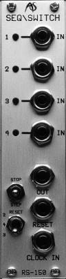
RS150
4 Channel sequential switch.
Consider each of the following three ideas:
• You want to create a sound whose fundamental character suddenly changes while you play it: not just in the sense of changing the modulation or the speed and depth of the envelopes, but by assuming a completely different timbre from that which went before.
You want to create a sound whose modulations change radically and unexpectedly as it develops, cycling between a number of complex modulating waveforms.
You want to choose between different sequences of notes - maybe to extend a melody, or to provide a variety of harmonic backgrounds.
These are very different concepts, but they share a fundamental property: each requires that something in the sound creation structure (the "patch") changes instantaneously and radically. Of course, modular synths give you a wide range of modulators and envelopes, but this is something different. It requires a device that allows you to take the outputs from a number of sources within the synthesiser, and route just a single desired signal (whether a CV or audio) to the next module in the chain. This device is called a Sequential Switch.
Armed with such a switch you can achieve each of the effects described above.
If the inputs to the Sequential Switch are the raw sounds generated by a variety of oscillators, the switch allows you to cycle between waveforms. (This is the concept from which wavetable synthesis was derived.)
If the inputs are a selection of modulating CVs, you can use the switch to select the desired modulator, applying each to the main signal for as long as desired.
If the inputs are the pitch CVs generated by a number of rows in an analogue sequencer, you can use the switch to jump between patterns.
There are, of course, many other uses for a Sequential Switch, and it can be one of the most creative modules within an analogue synthesiser.
IN USE
The Sequential Switch allows you to select between multiple inputs and
direct the chosen signal to the input of the next module in the patch.
Selection may be manual or may be triggered by the application of a
suitable clock or trigger pulse.
INPUT 1, 2, 3 & 4
Each input will accept any signal produced by the RS Integrator. These signals may be CVs or audio, and will lie in the range ±10V. If external signals are applied to the RS150's inputs they should also lie within these ranges.
STOP / RUN
/ STEP
Selects the mode of operation of the Sequential Switch.
STOP
The Switch directs the signal presented to the currently selected input to
the output.
RUN
With a suitable signal applied to CLOCK IN, the Switch will cycle between
the INPUTs, directing the signal at each in turn to the OUTPUT.
STEP
Manually cycles the INPUTs. If desired, you can use this to "fine
tune" each input prior to selecting RUN.
RESET 2 / 4
/ 3
Selects the final step before the cycle repeats.
2
Once step 2 has been reached, the next STEP or clock/trigger will return the
Switch to step 1. The input selection cycle is, therefore:
1-2-1-2-1-2-1-2-1-2-1-2… etc.
4 Once step 4 has been reached, the next STEP or clock/trigger will return the Switch to step 1. The input selection cycle is, therefore: 1-2-3-4-1-2-3-4-1-2-3-4… etc.
3
Once step 3 has been reached, the next STEP or clock/trigger will return the
Switch to step 1. The input selection cycle is, therefore:
1-2-3-1-2-3-1-2-3-1-2-3… etc.
CLOCK
IN
Provided that the STOP/ RUN / STEP switch is set to its middle position, the
RS150 will step through the inputs each time that a clock/trigger pulse
in the range 1V - 10V is detected at the CLOCK IN. The nature of the
Switch Sequence is determined by the RESET 2/4/3 switch.
RESET
The RS150 will return to step 1 whenever a clock/trigger pulse in the range
1V - 10V is detected at the RESET input.
OUT
The signal at the selected INPUT is always directed to the OUT socket.
INPUT LEDs
One of the input LEDs will
be lit at all times. This shows the active INPUT.
Note: The RS150 is not bi-directional. You can not use it to direct a single input to one of four outputs.