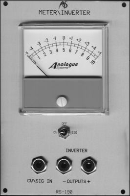
RS190
VU Meter / Inverter Module
It can be very useful to know the voltage being produced by any module within the Integrator. This can help you to refine your patches, and to check that modules are responding as you think they should.
IN USE
CV/Signal Input
The RS190 offers a single CV input that accepts and displays audio and CV signals in the ranges +/-5V and 0V to +10V.
CV Signal Switch
You may use this to select between10 CVs (DC and very low frequency signals) and audio.
CV
The module responds to DC and slowly varying signals, thus allowing you to
see the fluctuations in voltages created by devices such as envelope
generators.
Sig
The meter responds to, and displays the RMS value of AC signals. This means
that it is optimised for measuring the amplitudes of audio signals.
Off
The meter does not respond to incoming signals.
Outputs
The RS190 offers two outputs. These carry identical signals, except that the phase of one is inverted with respect to the other.
Output +
This outputs a signal identical to that received at the CV/Sig Input.
Output -
This outputs a signal that is inverted with respect to that received at the
CV/Sig Input.
Adjustment Screw
To calibrate the RS190 you should disconnect any inputs and position the needle at 0V using the white nylon screw.