RS200
3X8 Step Sequential Controller
It’s tempting to compare analogue sequencers to hardware MIDI sequencers, both rackmount and computer-based, if only because they are all capable of producing repetitive sequences and effects that can be modified in real-time. But, while a hardware MIDI sequencer can look like its analogue counterpart, it lacks one important facility inherent to analogue voltage control: you can’t add multiple MIDI controllers or use audio signals as modulators to create new effects.
Unfortunately, vintage analogue sequencers from companies such as ARP and Korg sell for hundreds of pounds, and you’ll be lucky to get change from £1,000 if you want an original Moog sequencer. Worse still, these originals are becoming increasingly rare, and by modern standards they can be rather limited. This is why the RS Integrator has a dedicated analogue sequencer, the RS200. Not only does it eliminate the need for a vintage unit if you want to create sequences with the Integrator itself, the RS200 will (with an RS10 or RS15 case) function as a self-contained unit capable of controlling almost all other analogue monosynths.
IN USE
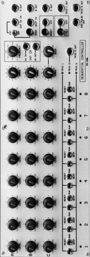
The RS200 is by far the most complex module within the RS Integrator series.
Its key features are:
Three rows
of 8-step CV generators with individual CV ranges and CV outputs for each
row
Independent trigger outputs for each of rows 1, 2 and 3
Internal clock with external CV input and clock output
External clock input and manual step function
Slew generator for portamento and other effects
Skip, Reset, and Stop/Start functions with independent CV inputs
End of sequence pulse output
LEDs to indicate sequence position and trigger status on each step.
To aid
understanding about each of these we will divide this chapter into four
parts, as follows:
1. Quick Tour
2. The Sequence Steps
3. Inputs, Outputs, And Other Controls
4. Some Ideas To Get You Started
1. QUICK TOUR
If you are impatient to hear some immediate results using your RS200 within a suitably configured RS Integrator the following instructions should have you up and running within a few minutes. If you are using the RS200 to control an external synthesiser please make allowances for the different names and configurations that you might encounter.
1.
Connect the A OUT output on your RS200 to the CV-IN of an RS90 VCO or the
CV-IN 1V/oct input of your external synth.
2.
If necessary, connect the TRIGGER 1 OUT output to the GATE-TRIG IN on your
RS60 Envelope Generators, or to the GATE input of your external synth.
Make sure that the Integrator or the external synth are set up so that
you can hear a sound even when no trigger is received. On an Integrator
you do this by setting the INITIAL LEVEL of an RS180 VCA to any value
greater than zero.
3.
Returning to the RS200, decide how many steps you wish to use and set the
step at which the sequence will loop by switching the appropriate RESET
switch to its upper position. For example, if you want your sequence to
be four steps long, raise the RESET switch at step 5. Set all
other RESET switches to their central RUN positions.
4.
If necessary, decide which steps will send triggers by setting the TRIGGER
switches (these are the ones to the left of the RESET switches) to
their upper positions.
5.
Set the CLOCK EXT/INT switch to its central position.
6.
Press the RESET button to initialise the sequence at step 1. The red LED at
'1' will light up to indicate that this is the step currently
active.
7.
Set Row A's RANGE control so that meaningful pitches are obtained from your
synthesiser when Row A's LEVEL control is swept from its fully
anticlockwise to its fully clockwise positions.
8.
Work your way through the sequence using the STEP button and set the pitches
using Row A's LEVEL (voltage control) knobs.
9.
Switch the EXT CLOCK IN switch to INT (internal).
10.
Press the STOP/START button to start the sequence.
11.
Adjust the speed of the internal clock using the FREQUENCY knob. 11.
Have fun!
2. THE SEQUENCE STEPS
The number of steps in your sequence and the outputs determined by each are defined by the eight columns (called "steps") marked 1 to 8. Each step has five controls and one indicator, as follows:
The
Knobs:
(i)
Row A LEVEL Controls These set the voltage created by Row A at each
step of the sequence. Their range is 0V to +10V, but their operation is
modified by the Row A RANGE control (see below).
(ii)
Row B LEVEL Controls These set the voltage created by Row B at each
step of the sequence. Their range is 0V to +10V, but their operation is
modified by the Row B RANGE control (see below).
(iii)
Row C LEVEL Controls These set the voltage created by Row C at each
step of the sequence. Their range is 0V to +10V, but their operation is
modified by the Row C RANGE control (see below).
The
Switches: (iv) RESET/RUN/SKIP switches
The eight switches each
offer 3 basic functions:
Reset
The sequence will run from step 1 to step 8 then loop back to step 1 unless
one of these switches is in the RESET position, in which case the
sequence will loop at the step before the RESET.
Run
The step is included in the sequence. This is called ‘free running’.
Skip
The step is excluded from the sequence, and the sequence jumps directly from
the previous step to the next.
Note: The SKIP position has another function when used together with the SKIP IN input described in the next section. If you want SKIP to function as described here but it is not doing so, check that you do not have a CV connected to SKIP IN.
(v)
TRIGGER switches These are the unlabelled switches immediately to the
left of each step's RESET/RUN/SKIP switch. Each has three
positions:
Up
A trigger is produced at this step and output from the TRIG 1 OUT
socket.
Centre
No trigger is produced at either output TRIG 1 or TRIG 2 at this step.
Down
A trigger is produced at this step and output from the TRIG 2 OUT
socket.
Note: A trigger is produced at the TRIG 3 OUT on every step regardless of all other settings. Amongst other uses this acts as a 'trigger THRU' socket when the RS200 is clocked from an external source.
The Step
Indicators
(vi) The Step LEDs The eight step LEDs indicate the position of the
sequence. The position is always the same for rows A, B and C.
3. INPUTS, OUTPUTS, AND OTHER CONTROLS
The RS200's I/O panel offers a total of 13 sockets, of which five are inputs and eight are outputs. There are also five knobs, three buttons, one switch and three LEDs. Together these can control many aspects of a synthesiser’s operation, including but not limited to: pitch control, filter frequency modulation, and the timing of events.
Switch
Int/Ext Clock selector
LEDs
Trigger indicators
Inputs:
Internal Clock rate
External Clock input
Skip Step input
External Reset
External Start/Stop
Outputs:
CV A
CV B
CV C
Trigger 1
Trigger 2
Trigger 3
End of Row Pulse output
Internal Clock output
Knobs
CV A Range
CV B Range
CV C Range
Internal Clock frequency
CV C Slew rate
Buttons
Step Reset Stop/Start
The operation of the knobs, CV inputs, and the switch are closely interrelated, so it is not possible to describe each without referring to the positions/settings of others. Please bear this in mind when you consider the action of each of the controls.
The
Knobs
(i) The RANGE controls
CV RANGE
A
CV RANGE B
CV RANGE C
These determine the range of voltages controlled by the CV knobs in each of the three rows. With the RANGE in the 0V position, the positions of the CV knobs are irrelevant, and 0V is output by the row regardless of any other settings.
Note: The notation on the RANGE knobs is approximate, and does not ensure that the maximum frequency will increase in precise octave steps.
(ii) The
Internal Clock Frequency
The internal clock is a stabilised analogue squarewave LFO (low frequency
oscillator) which can output any frequency in the range 0.1Hz (one step
every ten seconds) to approximately 30Hz. When the clock switch (see
below) is set to INT (internal clock) the INT CK FREQUENCY
control determines the step frequency in each of the rows.
(iii)
Slew
The Slew control allows you to control the rate of change of control voltage
output by Row C. At its minimum, the slew time from note to note is
approximately 5mS. At its maximum setting, the slew time is
approximately 1S.
The Buttons
(iv)
Step
The STEP button is a 'momentary' button, or 'toggle'. When the Clock INT/EXT
switch is in its central position (the sequence is halted) pressing
STEP will move the sequence one position to the right. When the
sequence is on its last step (either step 8 or as defined by the RESET
switches) pressing STEP will return the sequence to step 1.
(v) Reset
Pressing RESET will always return the sequence to step 1. This action may be performed whether or not the sequence is running.
(vi)
Stop/Start
The STOP/START button is a 'toggle'. Provided that the other settings are
appropriate, pressing STOP/ START once will START the sequence. If a
sequence is already running, pressing STOP/START will STOP the
sequence.
The Switch
(vii) EXT/INT
Clock Selector
The clock selector has three positions:
Down (INT) The rate at which the sequence moves through the steps is determined by the internal clock.
Up (EXT) The rate at which the sequence moves through the steps is determined by an external clock pulse presented to the EXT CK IN socket.
Centre The sequencer is not clocked, and you must use the STEP button to move through the steps.
The LEDs
(viii) The Trigger Output
LEDs
TRIG
1
TRIG 2
TRIG 3
These give a visual indication of the triggers generated at each of the three TRIG OUTs. When any of the LEDs is lit a trigger is produced at the appropriate output.
The Inputs
(ix) INT CK
CV IN
You may apply a CV in the range 0V to +10V to control the internal clock
rate. Note that, whatever voltage you apply to the CV IN, the internal
clock will not exceed its minimum and maximum rates of 0.1Hz and
30Hz.
(x) EXT CK
IN
This input accepts signals with 'ON' amplitudes in the range +1V to +20V and
'OFF' amplitude of less than +1V.
If the input signal is pulse-like, the sequencer will move through the steps according to the timing of this signal. There is no practical limit to the frequency of the input signal. One advantage of this is the ability to clock the RS200 at audio frequencies, making it possible to use each of the three rows in the sequencer as an audio-frequency complex waveform generator.
(xi) SKIP
IN
This modifies the action of the SKIP position of the switches in each of the
Sequence Steps.
Normally, the sequencer will ignore any step that has the RESET/RUN/SKIP switch set to SKIP, and jump directly to the next step in the sequence. However, if you apply a CV in the range +1V to +10V to the SKIP IN input, the sequence will not SKIP the step, but hold it until the CV is removed.
The normal 'skipping' action is, therefore, just a special case of this: with no CV applied, the step is not held, and proceeds directly to the next.
(xii) RESET
EXT
If you apply a CV in the range +1V to +20V to the RESET EXT input, the
sequence will return to step 1 when the +ve going transition is
received. The sequence will remain at step 1 until the CV is removed.
(xiii)
START/STOP EXT
If you apply a pulse in the range +1V to +20V to the START/STOP EXT input,
the sequence will either start (if it is stopped) or stop (if it is
running) when the +ve going transition is received.
The
Outputs
(xiv) The CV Outputs
A OUT
B OUT
C OUT
The three rows of CVs determined by the LEVEL knobs in each of the steps (as modified by the RANGE controls) are produced at these outputs. The maximum CV range is 0V to +10V.
(xv) The Trigger Output
TRIG 1
OUT
TRIG 2 OUT
TRIG 3 OUT
The three sets of triggers determined by the TRIGGER switches are produced at these outputs. All triggers are +10V pulses.
Remember that Row 3 produces a trigger pulse at the TRIG 3 OUT on every sequence step, regardless of the other controls and switches.
(xvi) END
PULSE OUT
A single +10V pulse is produced at this output each time that the sequence
reaches its final step and resets to step 1.
(xvii) INT CK
CK OUT
The +10V squarewave clock signal generated by the internal clock is output
here.
Inserting a lead at this point does not break the internal circuit, and if the CLOCK SWITCH is set to INT the sequence will continue to operate as before.
4. SOME IDEAS TO GET YOU STARTED
If you are not fully acquainted with analogue sequencers and would like a few ideas to get you started, the following may be of some help. Of course, there’s no room to do more than scratch the surface of the RS200's possibilities in this manual, so remember: an open mind and some free experimentation can yield startling results. Here are some basic ideas:
If you have not already done so, set your RS200 and synthesiser up as described in the QUICK TOUR. Then…
Set up a sequence and apply an LFO to the INT CK CV IN. This modulates the speed at which the sequence runs.
Drive the EXT CLOCK IN at audio frequencies, and use the 8 steps to define a complex waveform. Direct this back to the synth as an independent oscillator. The shape is multi-stage and heavily quantised, so it has a rather 'digital' character quite unlike the standard oscillators in your RS Integrator.
Use the TRIGGER switches creatively. Trigger outputs are used primarily to trigger the synthesiser’s envelopes. You can manipulate your sequence in real-time by switching the trigger switches between trigger ON and OFF whilst the sequence is playing. If triggers are placed at the beginnings of some notes and not others it will give a more human feel to the sequence, analogous to guitarists who pluck or hammer strings at the beginnings of some notes but not others.
Use other RS Integrator modules such as the RS280 Divider module to create complex timing changes within your sequences. For example, connect the INT CK CK OUT to the CK/SIG IN of the RS280, and return the _16 output from the RS280 to the START/STOP EXT input on the sequencer. This will cause the sequence to stop every 16 steps, and then restart after an interval of a further 16 clock pulses. Each time the sequence runs, it will start one step further to the right, creating complex changes in your music.
Use an RS150 Sequential Switch to extend your sequences to 24 steps. You do this by connecting CV A OUT to IN1 on the Sequential Switch, CV B OUT to IN2, and CV C OUT to IN3. Then connect the END PULSE OUT on the sequencer to the CLOCK IN on the Sequential Switch. Now, each time the sequencer reaches step 8 it will send a pulse to the switch advancing the input by 1.
Put all the RESET/RUN/SKIP switches to the SKIP position. Now apply noise from an RS40 Noise Generator at the SKIP IN input. This will make the sequencer step randomly, apparently moving backwards as well as forwards within the sequence. This is truly random note selection, and can be used in a number of ways to create quasi-melodies, generate harmonic structures, or provide sound effects.
Again, put all the RESET/RUN/SKIP switches to the SKIP position. Take noise from the RS40 and band-pass filter it using an RS110 Multimode filter. Apply the resulting signal to the sequencer's EXT CK IN to create random timing effects. You can even modulate the filter to modulate the speed of the randomised clock.
Just as an analogue synthesiser has an infinite number of possibilities, so does an analogue sequencer. The seven ideas above merely give you an idea of the types of sounds and effects you can create with the RS200. The rest is up to you!