RS310
Reverb \ Chorus
INTRODUCTION
Almost without exception, raw audio signals benefit from treatments that add movement within - or ambience to - the sound, so engineers have developed many devices to achieve such effects. Tape Echoes were among the earliest of these, and these used tape loops running past multiple record/ replay / erase heads that added discrete echoes to a signal.
The early 1970s saw an explosion of affordable devices that used cheap analogue delay lines to generate their sounds. Unfortunately, the delay times available from these were usually limited to a handful of milliseconds. This meant that they were unsuitable for imitating the luxuriant Grand Canyon effects of tape echo machines and digital echo units. Rather, they were more suited to creating flanging and chorusing (where the required delays are shorter) as well as short reverberant effects.
However, no matter what they were called, all these effects used the same basic building blocks. The first was an input circuit that accepted the source signal and split it into two parts: an untreated - or "dry" - signal that passed directly to the output; and a second signal that was delayed by the unit. The next building block was the delay circuit itself, and this almost always incorporated some form of modulation that changed the delay time (and therefore the pitch) of the signal passing through it. Finally, a mixer recombined the original and delayed parts of the signal, and it was here that they interacted to create the final effect.
It is important that you do not confuse an analogue module such as the RS310 with a mechanical reverberator (a spring reverb or plate reverb) or a digital reverb unit. The former of these use the properties of vibration within solid objects, while the latter use powerful digital processors to imitate the natural reverberation of audio signals in enclosed spaces. But consider this: it is one thing to place an effects unit between a musical instrument and a mixer or amplifier. It is quite another to place it within the signal chain of a modular synthesiser where you can use it as part of the signal generation mechanism itself. You can use the RS310 in both these ways, and .this is one of its great strengths.
IN USE
The RS310 is a complex BBD (bucket brigade device) analogue delay line with variable feedback. Unlike the simpler BBDs found in other delays and comb filters, it incorporates six unrelated "taps" at quasi-random delay points and with differing output levels. This means that an impulse applied to the input will result in at least six discrete outputs in addition to the "dry" signal.
In normal use, the master clock runs at speeds exceeding 10kHz, and a low-pass filter ensures that clock noise is not presented to the output. However, you can extend the delay time using CVs (see below) and the clock will then stray down into audible frequencies. You should then use an external filter to remove the clock noise. Alternatively, you can use the clock as an additional, albeit unusual, sound generation mechanism..
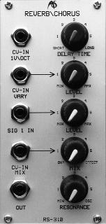
DELAY TIME and CV-IN FIXED
In normal use, the DELAY TIME control allows you to adjust the delay in the (approximate) range 2.5mS ("short") to 15OmS ("long"). You can modify this by applying a CV in the range +-10V to the CV-IN FIXED input. This allows you to drag the master clock right down through the audio band into subsonic territories. You can, therefore, use the RS310 as an audio signal generator, or even as an LF clock generator.
Note: Even without an applied CV; you will hear the high frequency tone generated by the delay line master clock when the DELAY TIME is set between "long" and approximately "2".
CV-IN VARY and LEVEL
You can modify the DELAY TIME by applying a CV to the CV-IN VARY input, and you can control the amount of its effect using the associated LEVEL control. This too allows you to drag the master clock down through the audio band into subsonic territories.
MIX and CV-IN MIX
The RS310 MIX control allows you to determine the amount of effected signal in the final output. At its furthest anticlockwise position only the "dry" signal passes, and no other control affects the output. As you rotate the MIX control clockwise, more and more "wet" signal is added until, at its furthest clockwise extreme, the delayed signal predominates. However, be aware that the dry signal is always present at the output - it is not removed as the wet signal is added.
You can modulate the MIX by applying a CV in the range +-10V to the CV-IN MIX input.
RESONANCE The RS310 has positive feedback from the output to the input. As you increase the amount of this feedback using the RESONANCE control, the RS310 will feed a greater and greater amount of the delayed signal back to the input.
At minimum RESONANCE, the RS310 has zero feedback and, if you feed a simple click into the unit, it will generate a single set of delays. As you increase the RESONANCE, more of the output will be fed back to the input so that a succession of clicks becomes audible. At somewhere between the 12 o'clock position and maximum, the gain of the feedback circuit will exceed unity, and delayed signals will not fade away. Finally, as RESONANCE approaches its maximum, the RS310 will self-oscillate and generate a complex tone even in the absence of an input signal.
Inputs and Outputs
The RS310 has one audio signal input, SIG IN, with an associated LEVEL control. This accepts signals in the range +-10V. There is a single output that carries a signal in the range +-10V
EXAMPLE SETTINGS
Flanger
Set the DELAY TIME to "short", and apply a modulating sine wave or triangle wave CV to the CV-IN VARY input. This can be generated by an LFO , and should be in the range of a second or two. Adjust the CV-IN LEVEL control so that the DELAY TIME is swept smoothly within an appropriate range- normally this will mean a setting of approximately "1".
Set the MIX to "effect" and adjust the RESONANCE so that the effect is clearly audible but the RS310 does not self-oscillate. This setting will be approximately "3" on the scale.
You will find that the flanging effect is best heard with the input LEVEL set to about "3".
Chorus
Set the DELAY TIME close to "long", but do not allow clock noise to intrude on the signal. Apply a modulating sine wave or triangle wave CV to the CV-IN VARY input. Depending on the effect required, this should be in the range of about O.3Hz to a few Hz. Adjust the CV-IN LEVEL control so that the modulating level is very low and the DELAY TIME is swept very slightly. This will require a setting close to "0".
Set the MIX to approximately "3" and adjust the RESONANCE so that the effect is subtle - perhaps "2" on the scale.
You will find that the chorus effect is best heard with the input LEVEL set to about "3".
Short Echo/Reverb
Set the DELAY TIME as close as possible to '1ong" without clock noise intruding on the signal. No modulating CVs are required.
Set the MIX to approximately "2" and adjust the RESONANCE so that the effect dies away in a realistic fashion. This setting will probably lie in the range "1" to "2" on the scale. You can increase the density of the effect by increasing the MIX and RESONANCE settings, but you should not allow the unit to loop the echoes infinitely, or allow it to self-oscillate. You will find that the echo effect is best heard with the input LEVEL set to about "3".