![]()
![]()
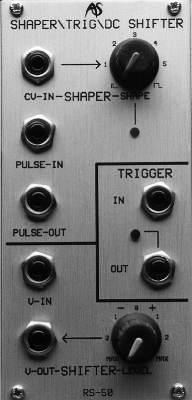
RS50
Trigger, Voltage Controlled Pulse
Shaper & Voltage Controlled DC Level Shifter
Trigger
Some analogue synthesisers generate pitch CVs and Gates, but not dedicated trigger signals. This can be frustrating when you use them to control modular synthesisers which can retrigger envelope generators and other modules during a sustained gate. What you need in these situations is a device that derives trigger signals from the signals provided.
On other occasions you may wish to step beyond the limitations imposed by conventional trigger generators such as keyboards, arpeggiators, and LFOs. You may, for example, like to trigger a synthesised sound in time with a drum beat. You may even wish to add a correctly timed filter response to the sound generated by the drums themselves. In each case, the Integrator needs to "know" when to trigger the envelope generators controlling the VCAs and VCFs in the patch.
The TRIGGER generator is the means by which you accomplish all these actions. For example, you can use it to detect changes in pitch CV in order to fire off trigger pulses in time with your playing. Alternatively, you can use it to detect changes in an external signal's amplitude and generate trigger pulses when these occur.
IN USE
The RS50 Trigger is
sensitive to any abrupt changes in voltage that exceed 10mV. Furthermore,
because trigger pulses are generated when the input is both
positive-going and negative-going, the RS50 will act as a clock-doubler,
generating pulses on both the leading edges and trailing edges of the
waveform.
I N
Accepts any signal in the
range ±10v.
OUT
Outputs a +10V pulse
whenever an abrupt change in voltage exceeding 10mV is detected at the
input.
LED
Gives a visual indication
of when triggers are generated at the output.
Shaper
Sometimes you may wish to take a short pulse and generate a more extended signal from it. For example, you may have a trigger (which is a pulse with virtually no duration) and want to create a gate signal from it. One occasion for this will be when you have derived a trigger using the RS50 Trigger described above. If you take the output from the Trigger to a multiple, and bring one output back to the Shaper, you can generate both gate and trigger simultaneously. Used together with an RS30 Frequency-to-Voltage converter, you can derive the full set of pitch CV, Trigger and Gate from a single audio signal.
This is not the only use for the Shaper, and different effects are obtained when you present audio frequency signals to its input. If the 'Shape' is at its minimum, low-ish frequencies will be re-transmitted as pulse waves. But if the duration of the Shape is longer, cycles of the incoming signal will be missed and, depending upon the nature of the original signal and the settings of the RS50, you can obtain many 'sync', pitch-shifting, and poly-rhythmic effects.
IN USE
The Shaper recognises the
leading edges of signals presented to its input and generates pulses of
specified durations at its output. You can control these durations
manually or with a Control Voltage.
PULSE-IN
The input accepts any
signal and derives pulses from leading edges in the range +2V to +20V.
SHAPE
SHAPE allows you to
determine the duration of the output pulse. At its minimum (with the knob
turned fully anticlockwise) the duration is approximately 4mS, allowing
frequencies of up to 250Hz (close to middle 'C') to be regenerated. At
its maximum (fully clockwise), the duration is longer than 1S.
CV-IN
You can modify the pulse
duration using a CV. A positive voltage applied at CV-IN widens the pulse.
A negative voltage narrows it.
PULSE-OUT
The Shaper generates a +10V
pulse wave at its output.
LED
The LED gives a visual
indication of the pulse width generated at the output.
Shifter
If a signal is not fluctuating between two levels it is called a DC voltage and, while you may think that this signal is less useful than the AC voltages generated by oscillators and LFOs, you would be wrong. For example, the knobs that allow you to tune a VCO or set the initial cutoff frequency of a VCF are sources of DC voltages that modify the action of the oscillator or filter (or whatever). It is often useful, therefore, to have an independent source of DC voltages that you can use to affect other modules. The RS50 "Shifter" is such a source.
Non-varying DC signals are not the only places in which you will find DC voltages. Consider the following example:
An LFO is adding vibrato to a signal. The amplitude of the LFO signal is approximately ±0.1V, thus making the width of the vibrato somewhat more that a semitone either side of the initial pitch. But what if the patch is synthesising a guitar sound? Guitarists' vibrato can only be above the initial pitch, never below it.* So, to obtain the same amount of vibrato, but only above the starting pitch, you add a DC offset of +0.1V to the LFO voltage, thus making it fluctuate in the range 0V to +0.2V. Again, the RS50 Shifter is the means by which you do this.
* Actually, this is not strictly true… the inappropriately named 'tremolo' arm, or 'whammy bar' can be used to shift the pitch down as well as up.]
There are many other uses for DC shift. Imagine taking an audio signal of amplitude ±8V and passing it through an RS100 low-pass filter. Now consider placing the DC Shifter in the signal path and applying a shift of +4V. The audio signal now lies in the range -4V to +12V. Since the RS100 only accepts signal in the range ±10V, clipping will occur in the positive part of the waveform, leading to some dramatic timbral changes. Furthermore, this clipping sounds subtly different to the clipping distortion generated by feeding a ±12V signal to the same input. Clearly, there are many uses for something as simple as a DC shifter.
IN USE
You can use the Shifter in
three ways: (1) to add a DC component to a signal, (2) to modify the
DC component of a signal, or (3) as a stand-alone generator of DC
voltages.
V-IN
Accepts the signal to be DC
shifted.
LEVEL
At its maximum
anticlockwise position, this will apply a DC shift of -10V to the signal
presented to V-IN. If you rotate the LEVEL control clockwise the
applied shift will increase until, at the 12 o'clock position, there is
no shift added. Continue rotating the knob clockwise and the shift will
increase further until, at its maximum clockwise extreme, a shift of
+10V is applied.
If no signal is presented to V-IN, a DC signal in the range ±10V will be generated at the output. In this case, the LEVEL knob may be used as a simple controller.
V-OUT
Outputs the resulting
signal. The maximum range of this output is itself ±10V.