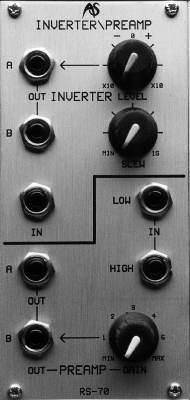
RS70
Pre-Amplifier And Inverter Slew Module
INTRODUCTION
An inverter is an example of a 'Voltage Processor'. It produces no signal of its own, but affects those presented to its input. The result of the process depends upon the nature of the source signal and, since CVs as well as audio signals may be inverted, a wide range of effects can be generated.
For example, you could present a keyboard CV to the Inverter. This means that, as you play up the keyboard (and, therefore, as the keyboard CV increases) the voltage generated by the inverter will decrease. One obvious use for this is to make the pitch of an oscillator descend rather than ascend as you play up the keyboard. Alternatively, you could also pass the inverted CV to a VCA so that high notes are quieter than low ones. This allows you to cross-fade between sounds as you play different notes.
You can also invert audio signals so that the resulting signal is 'out of phase' with respect to the original. On its own, this has no audible effect, but when the signals are combined they can create cancellation and 'phasing' effects. Modulating and/or delaying one of these signals generates many other complex sounds.
IN USE
I N
The input accepts any
signal in the range ±10v. Signals ranging from DC to over 20kHz may be
presented, but only those below approximately 10kHz will be passed to
the output.
LEVEL
At the maximum anticlockwise setting of the LEVEL control, the Inverter will
generate an inverted signal 10 times the amplitude of the input
signal.
As you turn the control clockwise, the signal will remain inverted but the gain will steadily decrease until, at the 12 o'clock position, the input is fully attenuated and no output is generated.
If you continue to turn the LEVEL control beyond the 12 o'clock position, the original signal will be passed without inversion. The amplitude of the output will increase from 0 until, at the maximum clockwise position, it will be 10 times the amplitude of the input signal.
SLEW
SLEW
acts upon rapid changes in the signal, slowing those changes by an amount
determined by the control. At its minimum, the slew rate is
approximately 0.1mS, thus allowing signals of up to 10kHz to pass
unimpeded. At its maximum slew rate of approximately 1 second, the slew will
provide portamento and other smooth transitions between voltages.
Slewing may be used to modify both CVs and audio signals, and the exact nature of the transitions is determined by the waveform of the signal presented. Portamento is a perfect example of slew applied to a CV: the slew circuit smooths the transitions between the stepped CVs normally used to determine pitch, thus making one note 'glide' to the next rather than jumping abruptly as it would otherwise do.
Applying slew to audio signal generates a quite different effect: it acts as a low-pass filter. This is because, above some frequency determined by the slew rate, the circuit can no longer reach the peaks and troughs of the signal before the next cycle is received. The higher the frequency presented to the input, the more the signal is attenuated, until DC is obtained. The frequency (in Hertz) at which the cut-off begins is the inverse of the slew rate (in seconds). On the RS70 the maximum slew rate is extremely fast, so the cut-off frequency reaches well into the audio band. This means that you can use the inverter in the RS70 as an auxiliary low-pass filter.
OUT
The Inverter provides two
outputs, marked 'A' and 'B'. These are identical, and you can use these
to direct the treated signal to two destinations simultaneously.
Pre-Amp
A pre-amp is the only module that, in normal use, amplifies signals within the Integrator. (Although VCAs are called "Voltage Controlled Amplifiers" they should, more accurately, be called "Voltage Controlled Attenuators".) A pre-amp is most often used to amplify weak external signals so that they can be correctly processed within the Integrator. The RS70 will accept virtually any such signal, and it can also be used to amplify signals generated within the Integrator itself.
I N
Two inputs and provided:
LOW and HIGH. These are provided so that the widest range of signals can
be correctly treated. If you do not know the amplitude of the input
signal it is best to use the HIGH input and minimum gain. This will
minimise any possibility of distortion.
GAIN
The GAIN control ranges from approximately -2dB in its fully anticlockwise
position to +21dB in its fully clockwise position, depending upon the
input used.
The maximum signal level is ±10v peak-to-peak. If the amount of gain applied causes the signal to exceed this, clipping will occur. In other words, the amplitude of the resulting signal will not increase further, but the waveform will be affected, and distortion will occur. This distortion can be used creatively if you wish.
OUT
The Pre-Amp provides two outputs, marked 'A' and 'B'. These are identical,
and you may use them to direct the treated signal to two destinations
simultaneously.