Analogue Systems
RS-340
Gate Delay
Gate delay and trigger with reset feature.
There are occasions on which you may want to generate a Gate or Trigger at some specified time after a sonic event occurs.
This, for example, allows you to use two VCO/VCF/VCA signal paths - one slightly delayed with respect to the other - to create a single, composite sound each time that you press a key. You could use one VCO/VCF/VCA path to place a "chiff" at the start of a flute or woodwind note, and the second to generate a sustained sound that imitates the body of the real instrument. Alternatively, you can use this technique to create interesting rhythmic structures in which one percussive sound is followed closely by another.
The problems encountered with triggering multiple sounds in this way are twofold. Firstly, you will often wish to initiate the second envelope very soon after the first - more quickly than is possible using your hands. Secondly (and even if the delay between the two Gates is long enough for you to initiate both manually) there's the problem of consistency: the relationship between the two parts of the sound must be the same for each note you play.
To solve these problems there's a dedicated module that will create the appropriate delayed Gates and Triggers for you. It's a Gate Delay.
In use :
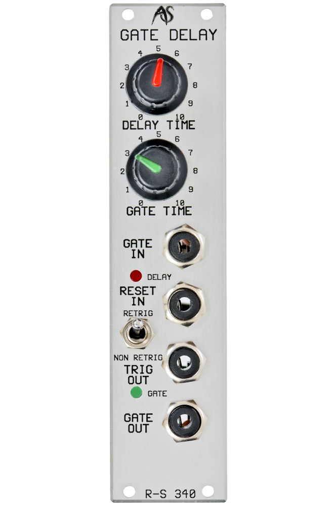
The RS-340 is a multi-mode Gate Delay module and Shaper that recognises any positive-going pulse exceeding +1V, and then generates a Trigger and a Gate of specified duration a user-defined time afterwards. Two LEDs offer visual feedback regarding the Gate status of the module.
GATE IN
This accepts a positive-going pulse in the range +1V to +20V to initiate the Gate Delay cycle.
DELAY TIME
This determines the length of time between receipt of the input pulse, and the output Gate and Trigger.
The minimum delay is 10mS. The maximum is 10S.
GATE TIME
The GATE TIME allows you to determine the duration of the generated Gate pulse. The minimum duration is 10mS. The maximum is 10S.
Status LEDs
Two LEDs give a visual indication of the state of the RS340 at any moment.
The green LED will be lit during the delay period.
The Red LED will be lit while the delayed Gate is 'High'.
TRIG OUT
This outputs a +10V pulse whose duration is determined by the GATE TIME control.
RESET IN
The RESET IN accepts a positive-going pulse in the range +1V to +20V to reset the Gate Delay cycle. This terminates the current Delay or Gate (depending upon where the module is in the cycle) and returns to "wait" for the next input pulse.
RETRIG / NON-RETRIG
The RS-340 offers two mode of operation:
- NON-RETRIG
Provided that no RESET pulse is received, the module always completes the full Gate Delay cycle, regardless of any further inputs at the Gate IN socket. - RETRIG
The module terminates the existing cycle, resets, and starts a new cycle whenever a pulse is received at the GATE IN socket.
The Gate Delay Used As A Pulse Shaper
Because a Gate Delay responds to brief incoming pulses and creates Triggers and extended Gates from them, you can also use it to derive high quality Gates from poor gate signals such as the outputs from envelope followers, and click tracks replayed from tape. This is necessary when you want to reshape an audio pulse into a form that the synthesiser can use for timing or retriggering purposes. For more information on this subject, you should also refer to the chapter on the RS-50 Shaper/Trigger/DC Shifter module.
Furthermore, you can use a Gate Delay to generate an extended but largely undelayed Gate whenever you present it with a Trigger or an audio click. You can use the output as a conventional Gate or as an extended Trigger. The latter will guard against false triggers caused by the abrupt end of an input click.
